IoT-PostBox v1.x

Complete technical documentation for IoT-PostBox v1.x series (ESP32-S2 based). This is the current generation with advanced features including dual connectivity, load sharing power management, and native USB programming.
Hardware Overview
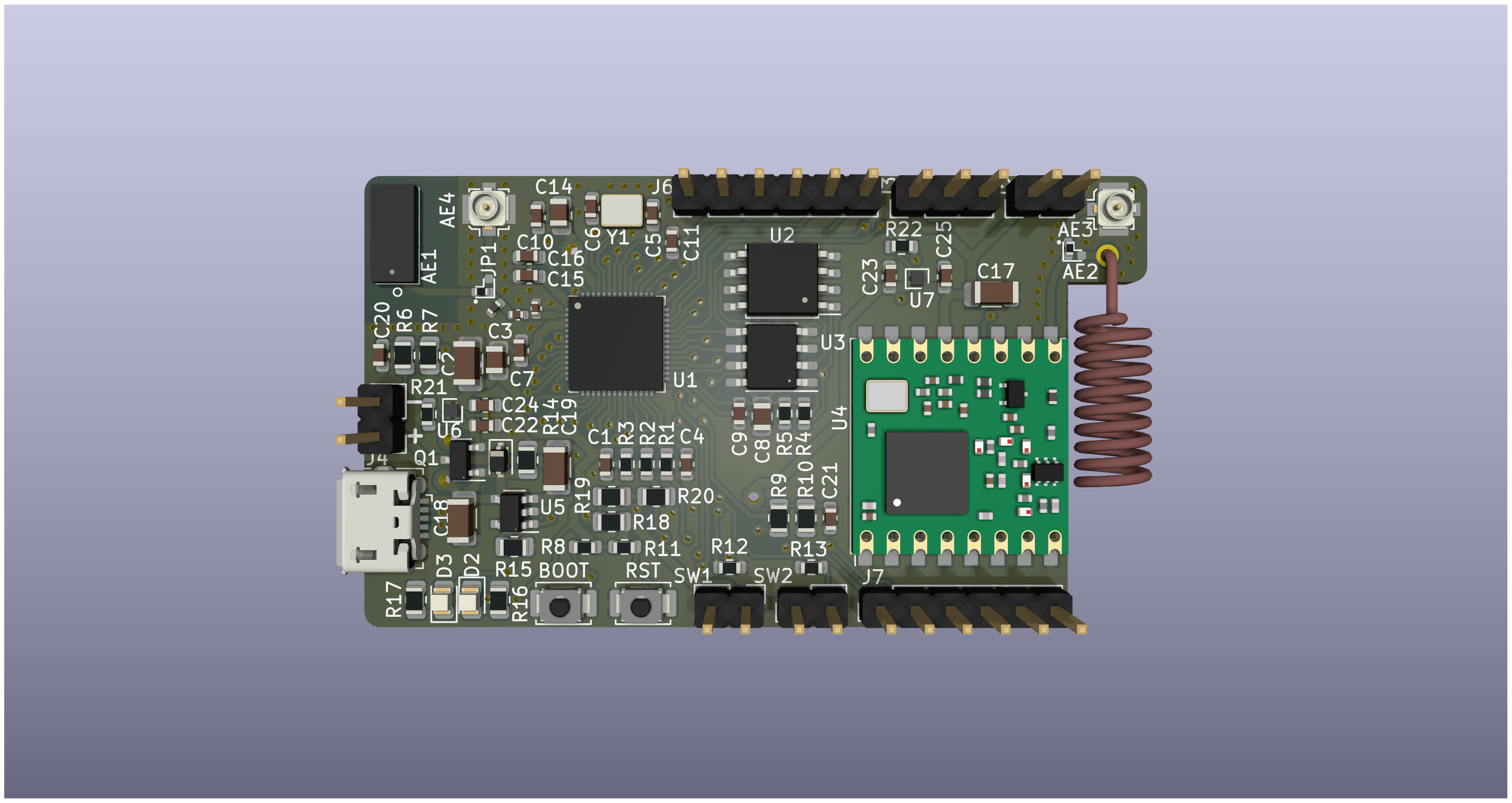
Key Features
Core Platform:
- MCU: ESP32-S2 with up to 16MB Flash + 8MB PSRAM
- Native USB: Direct programming and debugging via USB-C connector
- Dual Connectivity: WiFi (2.4GHz) + LoRaWAN (868/915MHz RFM95W)
- Wake-up Method: GPIO interrupt-based from deep sleep (vs hardware reset in v0.x)
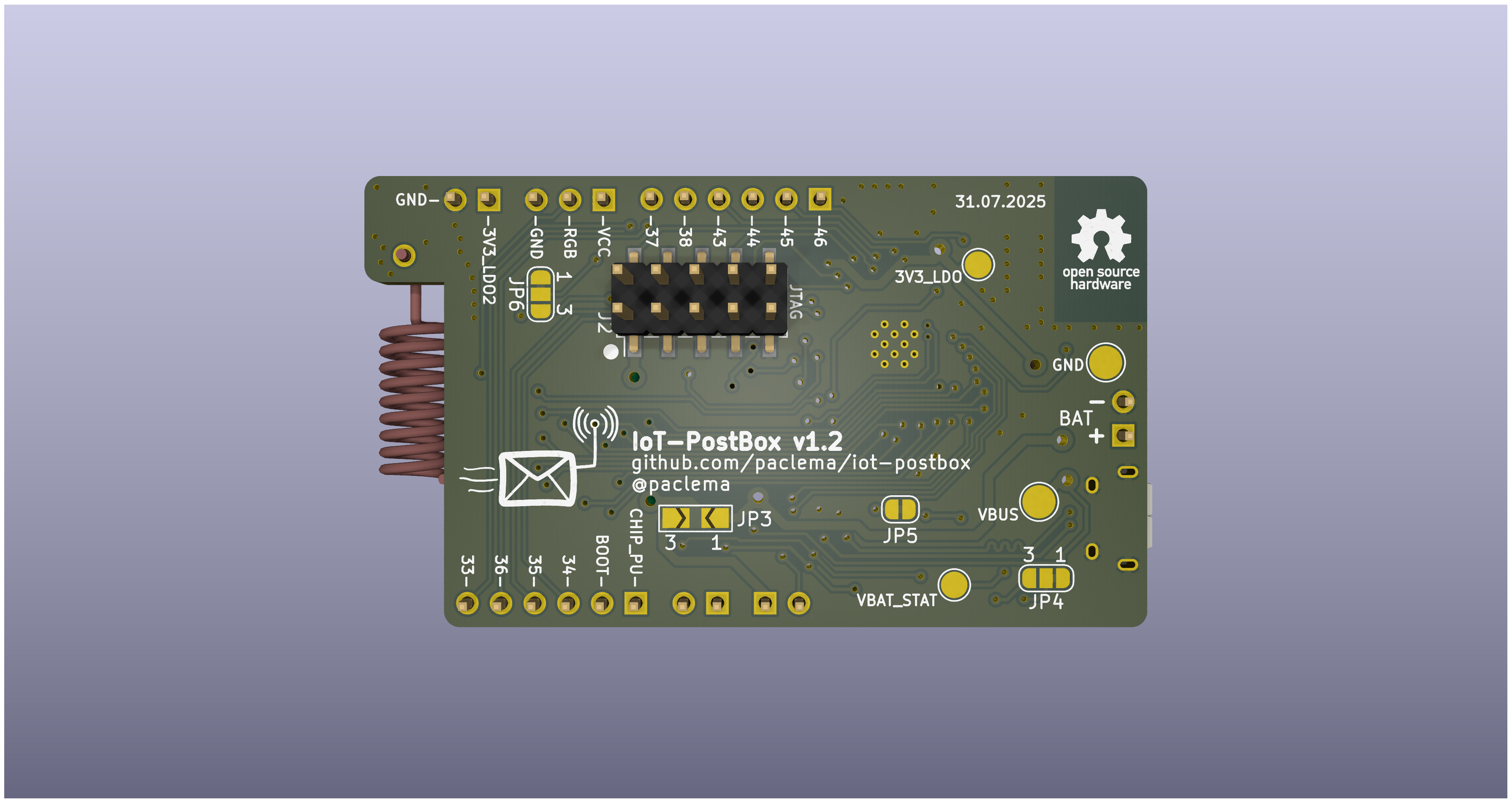
Power Management:
- Load Sharing Circuit: Automatically selects USB or battery power
- Dual LDO Design: Main (3V3_LDO) + Peripheral (3V3_LDO2) power domains
- Enhanced Monitoring: Dedicated ADC sensing for VBAT and VBUS voltages
- Smart Charging: Configurable charging current with multiple IC support
Connectivity & I/O:
- External Antennas: uFL connectors for WiFi and LoRaWAN (selectable via jumpers)
- Switch Sensors: Two GPIO interrupt-capable inputs (SW1, SW2)
- Expansion Ports: J6 (EXT1) and J7 (EXT2) with I2C, SPI, UART
- LED Support: Dedicated port for RGB LED strips (J3)
- Debug Interface: JTAG connector for advanced debugging
Power Management Architecture
Load Sharing System
The IoT-PostBox v1.x series features an advanced power management system that intelligently manages power sources:
USB 5V ──┬── Charger IC ──── Li-Po Battery (3.7V)
         │
         └── Load Sharing Circuit ──┬── Main LDO (3V3_LDO) ──── MCU & Core Systems
                                    │
                                    └── Peripheral LDO (3V3_LDO2) ──── LED Strip & EXT Ports
Key Benefits:
- Seamless Power Source Selection: USB power when connected, battery when disconnected
- Continuous Operation: Device remains powered during charging cycle
- Dual Power Domains: Core systems and peripherals on separate LDO rails (700mA each)
- LDO Protection: Current overload, output short circuit, and overheating protection
- Battery Protection: Overcharge, overdischarge, and reverse polarity protection via charger IC
Battery Charging Configuration
The charging system supports multiple charger ICs with configurable current using the RPROG resistor:
Supported Charger ICs:
- MCP73831/2: Max 500mA charging current
- TP4054: Max 800mA charging current
- TP4065: Max 600mA charging current
RPROG Resistor Selection:
MCP73831/2(max 500mA) orTP4054(max 800mA):
$$I_\text{charge} (\mathrm{mA})= \frac{1000~(\mathrm{V})}{R~(\mathrm{k}\Omega)}$$
| RPROG (Ω) | Charging Current (mA) |
|---|---|
| 10k | 100 |
| 5k | 200 |
| 2k2 | 455 |
| 2k | 500 |
TP4065(max 600mA):
$$I_\text{charge} (\mathrm{mA})= \frac{1100~(\mathrm{V})}{R~(\mathrm{k}\Omega)}$$
| RPROG (Ω) | Charging Current (mA) |
|---|---|
| 2k2 | 500 |
| 2k | 600 |
Charging Status Indicators:
- VBAT_STAT: Tri-state (MCP73831) or Open-drain (MCP73832, TP4054, TP4065) monitored using ESP32-S2 GPIO3/ADC1_CH2 pin.
- D2 (Orange LED): Charging in progress
- D3 (Green LED): Battery fully charged
- Both LEDs Off: No USB connected (device may be powered by battery)
Programming & Initial Setup
Hardware Setup:
- Power Connection: Connect USB-C cable to J4
- Boot Mode: Hold BOOT button while connecting USB for programming mode
- Driver Installation: Install ESP32-S2 USB drivers if needed
Firmware Upload:
# Using PlatformIO
pio run -e IoT-PostBox_v1 -t upload

# Using Arduino IDE
# Select "ESP32S2 Dev Module" board
# Select "USB CDC" for USB communication
Initial Configuration:
- WiFi Setup: Configure network credentials via web dashboard
- MQTT Settings: Set broker address and authentication
- LoRaWAN Setup: Configure DevEUI, AppEUI, AppKey (if using LoRaWAN)
Interactive Bill of Materials
Note
Explore components to view details and placement information. View Fullscreen 🔍
Technical Documentation
3D Model
Note
Explore the 3D model interactively. Use mouse to rotate, zoom and pan. View Fullscreen 🔍
Detailed Pinout Reference
Switch SW1 & SW2 Sensor Inputs
| Pin | Signal | Function |
|---|---|---|
| 1 | VCC | Reference voltage |
| 2 | SW1/SW2 | GPIO4/GPIO5 input for switch detection |
Typical Connection:
- Mechanical switches, hall sensors, or reed switches
- Pull-down resistors included on PCB
- Wake-up capable from deep sleep via GPIO interrupt
EXT1 Expansion Port (J6):
| Pin | Signal | Function |
|---|---|---|
| 1 | GPIO46 | Strapping pin (can be used for boot mode selection) |
| 2 | GPIO45 | Strapping pin (can be used for VDD_SPI selection) |
| 3 | GPIO44 | UART0 RXD |
| 4 | GPIO43 | UART0 TXD |
| 5 | GPIO38 | I2C SCL |
| 6 | GPIO37 | SPI MISO |
EXT2 Expansion Port (J7):
| Pin | Signal | Function |
|---|---|---|
| 1 | CHIP_PU | ESP32-S2 enable (power up, active high) |
| 2 | BOOT | Boot mode selection (GPIO0, strapping pin) |
| 3 | GPIO34 | SPI MOSI |
| 4 | GPIO35 | SPI SCK |
| 5 | GPIO36 | SPI CS |
| 6 | GPIO33 | I2C SDA |
LED & Power Output Connectors
LED Strip Port (J3):
| Pin | Signal | Function |
|---|---|---|
| 1 | VCC | Power for LED strip (3V3_LDO2) |
| 2 | RGB | PWM output for WS2812B/SK6812 RGB LED strip |
| 3 | GND | Ground |
Power Output Port (J5):
| Pin | Signal | Function |
|---|---|---|
| 1 | 3V3_LDO2 | Power output from peripheral LDO |
| 2 | GND | Ground |