IoT-PostBox v0.x
Legacy technical documentation for IoT-PostBox v0.x series (ESP8266 based). This generation focuses on ultra-low power consumption with hardware wake-up mechanism and basic WiFi connectivity.
Hardware Overview
| Top View | 3D Rendering | Bottom View |
|---|---|---|
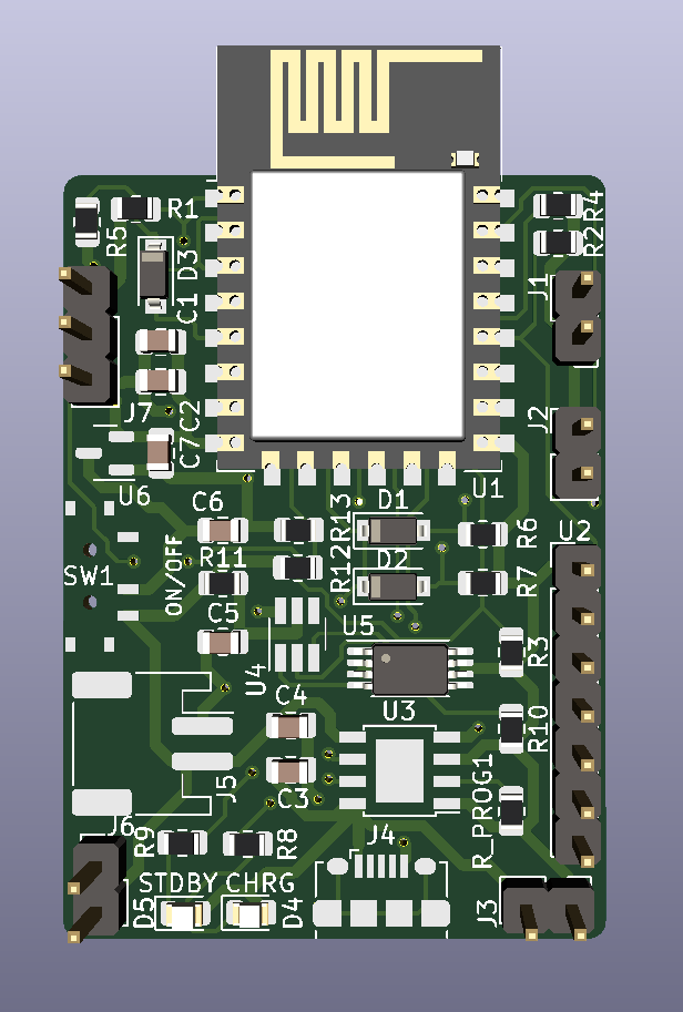 |
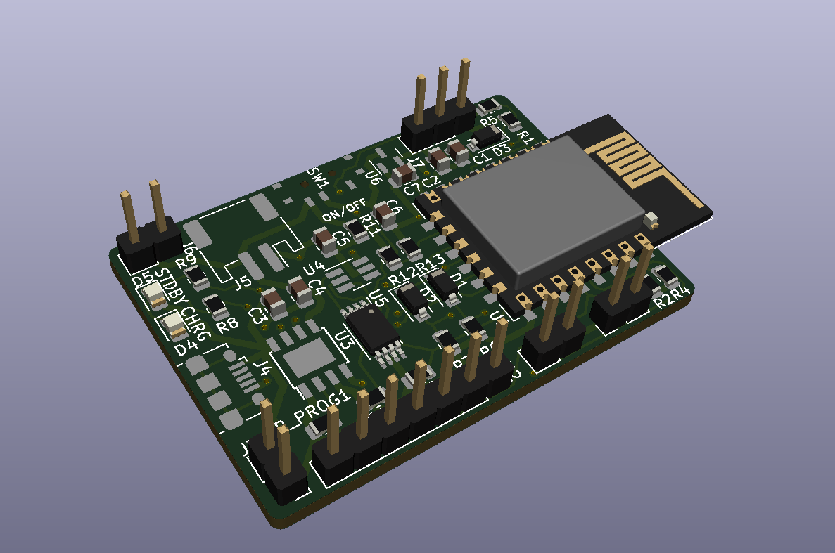 |
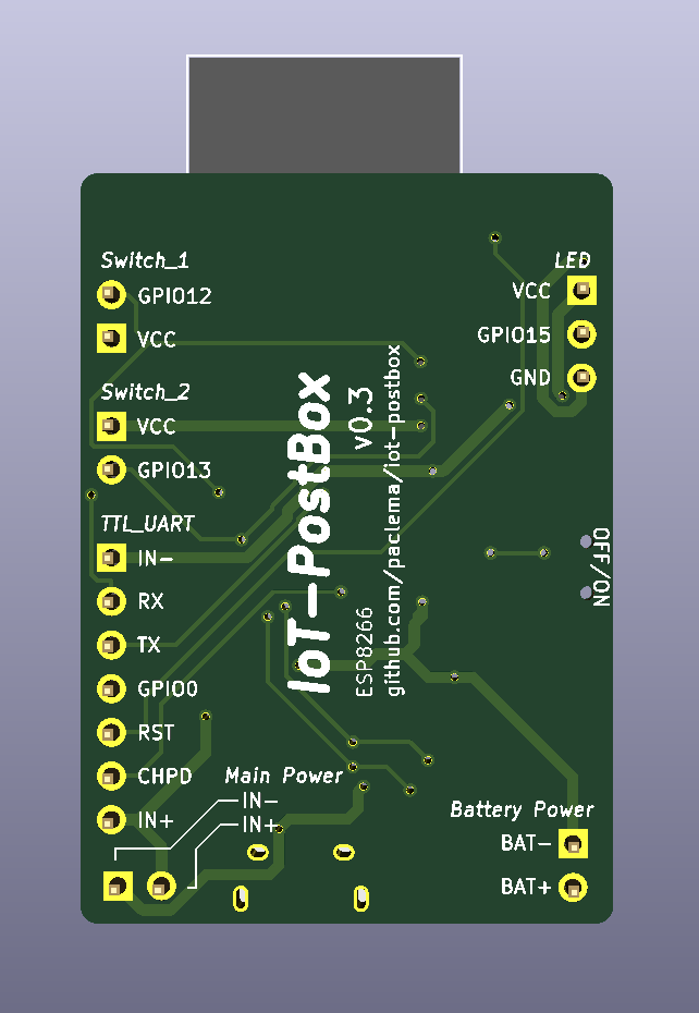 |
Key Features
Core Platform:
- MCU: ESP8266 (ESP-12F or ESP-07S)
- Connectivity: WiFi 2.4GHz with MQTT support
- Wake-up Method: Hardware reset via CH_PD pin (vs GPIO interrupt in v1.x)
- Power Optimization: Deep sleep with GPIO14 keep-alive mechanism
Power Management:
- Battery Charger: TP4056 with protection circuits
- Single LDO: ME6211 or MCP1700 for power regulation
- Battery Monitoring: ADC-based voltage sensing
- Protection: Overcharge, overdischarge, and overcurrent protection
I/O & Interfaces:
- Switch Sensors: Two hardware wake-up inputs (J1, J2)
- LED Support: WS2812B RGB LED strip (v0.3+)
- Programming: Populated UART and programming pins ready for external TTL-to-USB adapter
- Expansion: Basic GPIO access
Power Management Architecture
Hardware Wake-up System
The v0.x series uses a unique hardware wake-up mechanism optimized for ultra-low power consumption:
Switch Input ──── CH_PD Pin ──── ESP8266 Power Control
     │                                    │
     └──── GPIO14 ──── Keep-Alive Logic ──┘
Wake-up Process:
- Power Off State: ESP8266 completely powered down (CH_PD low)
- Event Detection: Switch contact pulls CH_PD high, physically powering on the ESP8266
- Keep-Alive Activation: Firmware immediately sets GPIO14 high to maintain CH_PD even if switch opens
- Notification Process: ESP8266 performs WiFi connection and sends MQTT notification
- Power Down: After configured time/completion, GPIO14 goes low, powering down the ESP8266
Power Management Options:
- Complete Power Down: GPIO14 low after notification (recommended for battery life)
- Deep Sleep Mode: Can be configured instead of complete power down
- Continuous Operation: GPIO14 remains high for always-on operation
Power Consumption:
- Power Off State: ~0μA (ESP8266 completely powered down)
- Active Mode: ~80mA during WiFi transmission
- Battery Life: Months to years depending on event frequency and configuration
Power Input Considerations
- Only one power source can be connected at a time: USB charging, J3 (PowerIn), or UART programming connector
- Connecting multiple power sources simultaneously can damage the board
- This simple design lacks protection against multiple power source conflicts
- Always disconnect one power source before connecting another
Battery Charging Configuration
TP4056 Charger IC:
- Input Voltage: 4.5V to 5.5V (USB 5V)
- Charging Current: Configurable via RPROG resistor
- Protection Features:
- Overcharge protection
- Overdischarge protection
- Overcurrent protection
- Battery reverse polarity protection
RPROG Resistor Selection:
$$I_{charge} = \frac{V_{PROG}}{R_{PROG}} \times 1200 \quad (V_{PROG}=1V)$$
| RPROG (kΩ) | Charging Current (mA) |
|---|---|
| 10 | 130 |
| 5 | 250 |
| 4 | 300 |
| 3 | 400 |
| 2 | 580 |
| 1.66 | 690 |
| 1.5 | 780 |
| 1.33 | 900 |
| 1.2 | 1000 |
Programming & Initial Setup
Hardware Requirements
Programming Methods for ESP8266:
Option 1: TTL-to-USB Adapter
- Repository: iot-postbox/ttl_to_usb_adapter
- Purpose: Converts DTR/RTS signals to ESP8266 boot sequence
- Features:
- Automatic boot mode selection via DTR/RTS
- CH_PD control via dedicated jumper
- Works with any FTDI breakout board
Option 2: Integrated USB Bridge
- Alternative: USBtoUART Bridge - Complete USB programming solution
- Advantage: Single device solution with integrated USB-to-UART conversion
Connection: UART pins populated on PCB for direct programming interface
Programming Setup:
Option 1: Using TTL-to-USB Adapter
- Connect FTDI Breakout: Attach a USB to UART FTDI breakout board to TTL-to-USB adapter
- Connect to PCB: Attach adapter to ESP8266 UART pins on PCB port
- Set Boot Mode: Configure adapter jumper for programming mode
- Upload Firmware: Use Arduino IDE or PlatformIO
Option 2: Using Integrated USBtoUART
- Direct Connection: Connect USBtoUART bridge directly to ESP8266 UART pins
- Automatic Boot: Device handles boot sequence automatically
- Upload Firmware: Use Arduino IDE or PlatformIO
Firmware Configuration
Arduino IDE Setup:
// Board: "Generic ESP8266 Module" or "NodeMCU 1.0"
// Flash Size: 4MB (depending on ESP variant)
// CPU Frequency: 80MHz (recommended for power efficiency)
PlatformIO Configuration:
[env:esp8266]
platform = espressif8266
board = esp12e
framework = arduino
Initial Setup:
- WiFi Configuration: Set network credentials in code or via captive portal
- MQTT Settings: Configure broker address and authentication
- Sleep Settings: Configure deep sleep duration and wake-up conditions
Interactive Bill of Materials
Note
Explore components to view details and placement information. View Fullscreen 🔍
Technical Documentation
3D Model
Note
Explore the 3D model interactively. Use mouse to rotate, zoom and pan. View Fullscreen 🔍
Detailed Pinout Reference
Switch Sensor Inputs
Event Detection Connectors (Switch_1 & Switch_2):
| Pin | Signal | Function |
|---|---|---|
| 1 | VCC | Reference voltage |
| 2 | GPIO | GPIO input for switch detection |
Connection Notes:
- Connect switch between VCC and GPIO pins
- GPIO detects circuit closure when switch is activated
- Circuit closure triggers CH_PD wake-up sequence
Power & Charging Connectors
Battery Connector (Battery Power):
| Pin | Signal | Function |
|---|---|---|
| 1 | BAT- | Battery negative (Ground) |
| 2 | BAT+ | Battery positive (3.7V Li-Po) |
External Power Input (Main Power):
| Pin | Signal | Function |
|---|---|---|
| 1 | GND | Ground |
| 2 | VBUS | External power input (5V) |
USB Charging:
- Connector: Micro-USB (depends on version)
- Input: 5V for charging and operation
- Current: Up to 1A charging (RPROG dependent)
LED Strip Connector (v0.3+)
WS2812B LED Strip (LED):
| Pin | Signal | Function |
|---|---|---|
| 1 | VCC | Power (3.3V) |
| 2 | GPIO15 | WS2812B data signal |
| 3 | GND | Ground |
Programming & Debug Interfaces
UART Pins Extension Port (TTL_UART):
| Pin | ESP8266 GPIO | Function |
|---|---|---|
| 1 | GND | Ground |
| 2 | RX | UART receive (GPIO3) |
| 3 | TX | UART transmit (GPIO1) |
| 4 | GPIO0 | Boot mode selection |
| 5 | RST | Hardware reset |
| 6 | CH_PD | Chip enable |
| 7 | 3V3 | Power supply |