USBtoUART

A compact USB-C to UART bridge board based on the Silicon Labs CP2102N chip and featuring a dedicated XC6220B331ER LDO regulator, designed for debugging, programming, and serial communication with microcontrollers and embedded systems.
Why this board? Unlike typical USB-to-UART bridges, this board features a dedicated LDO regulator that supplies up to 1A at 3.3V, ensuring stable power delivery to the target board while providing reliable data communication.
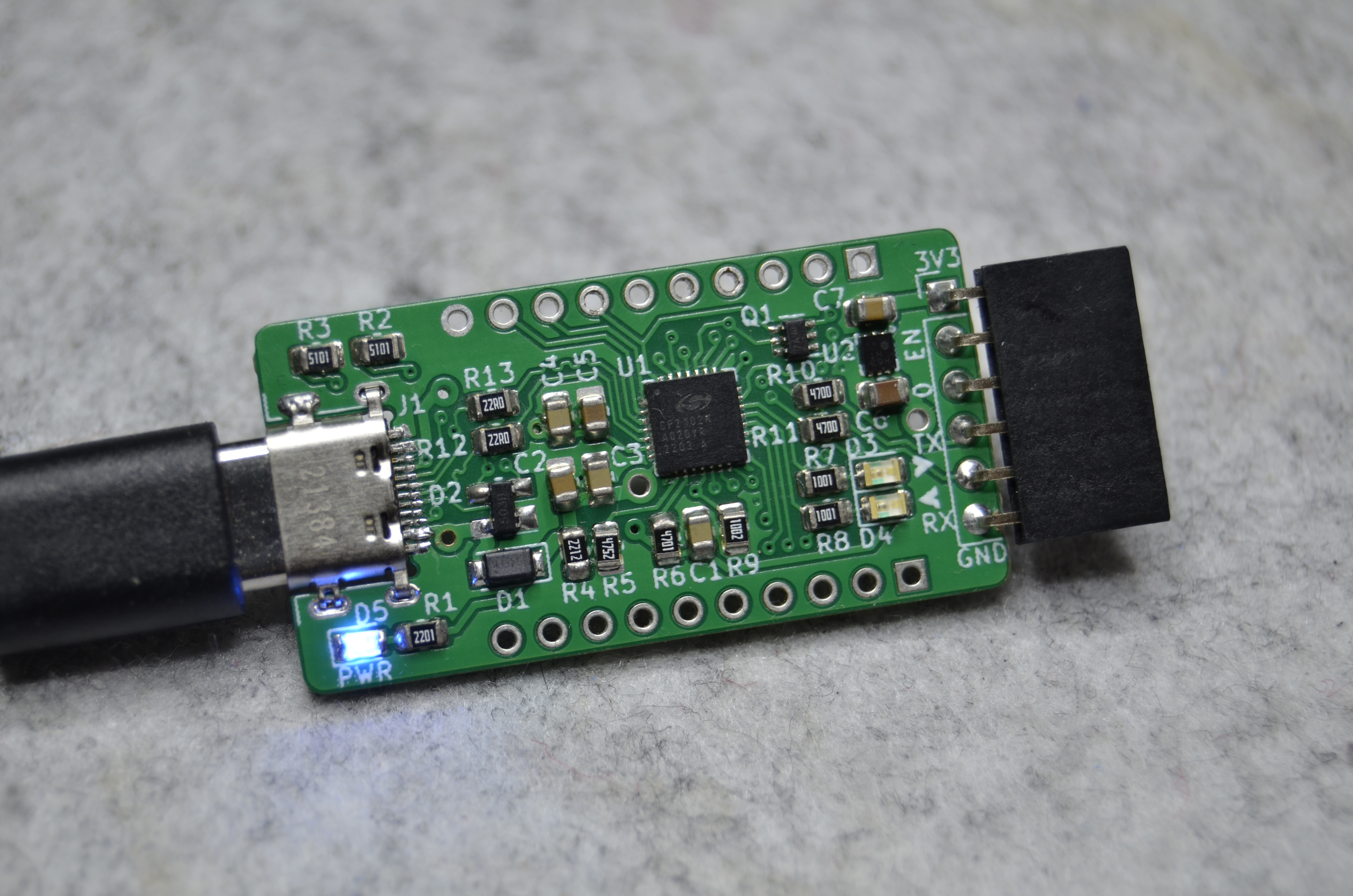
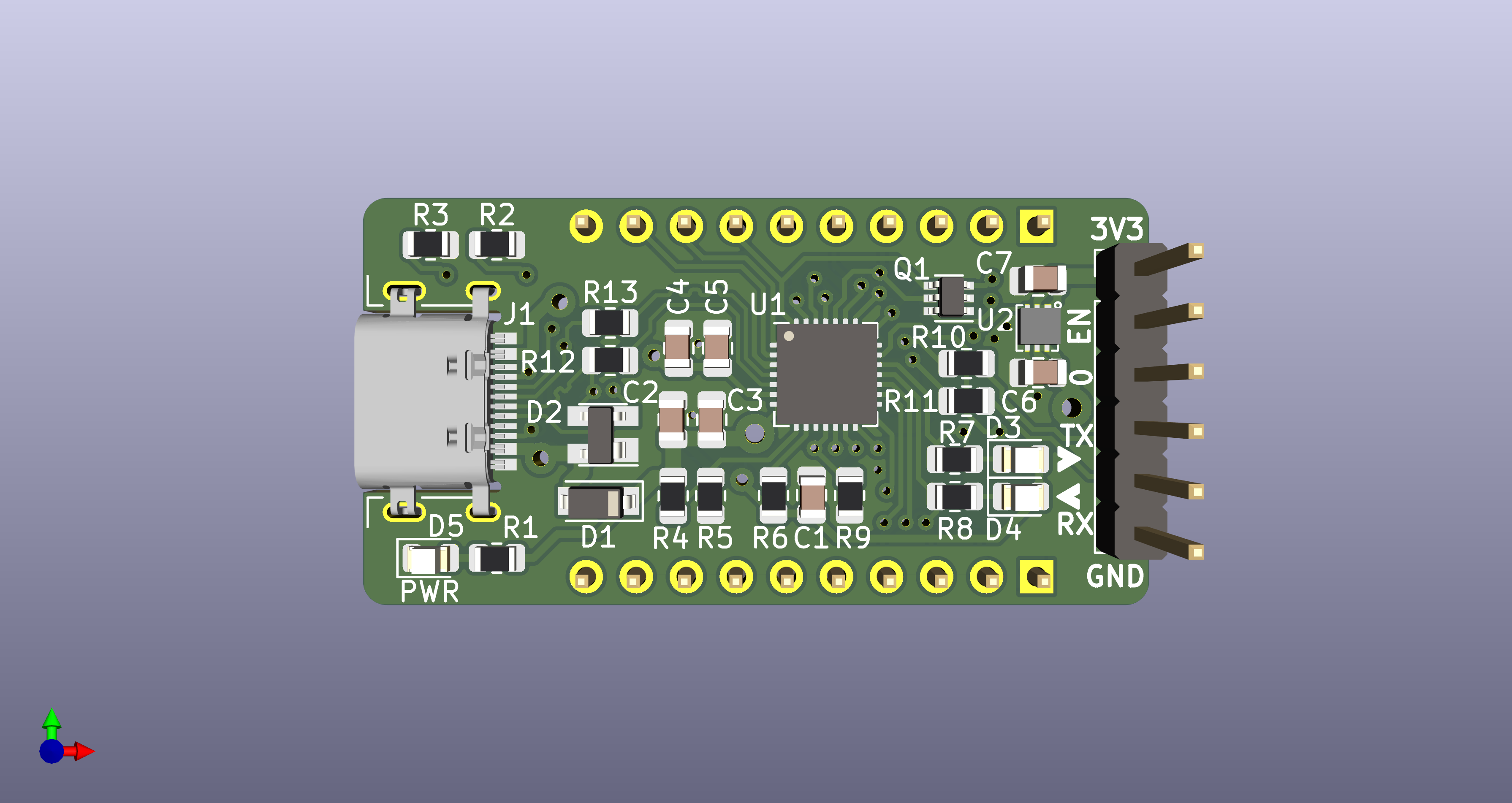
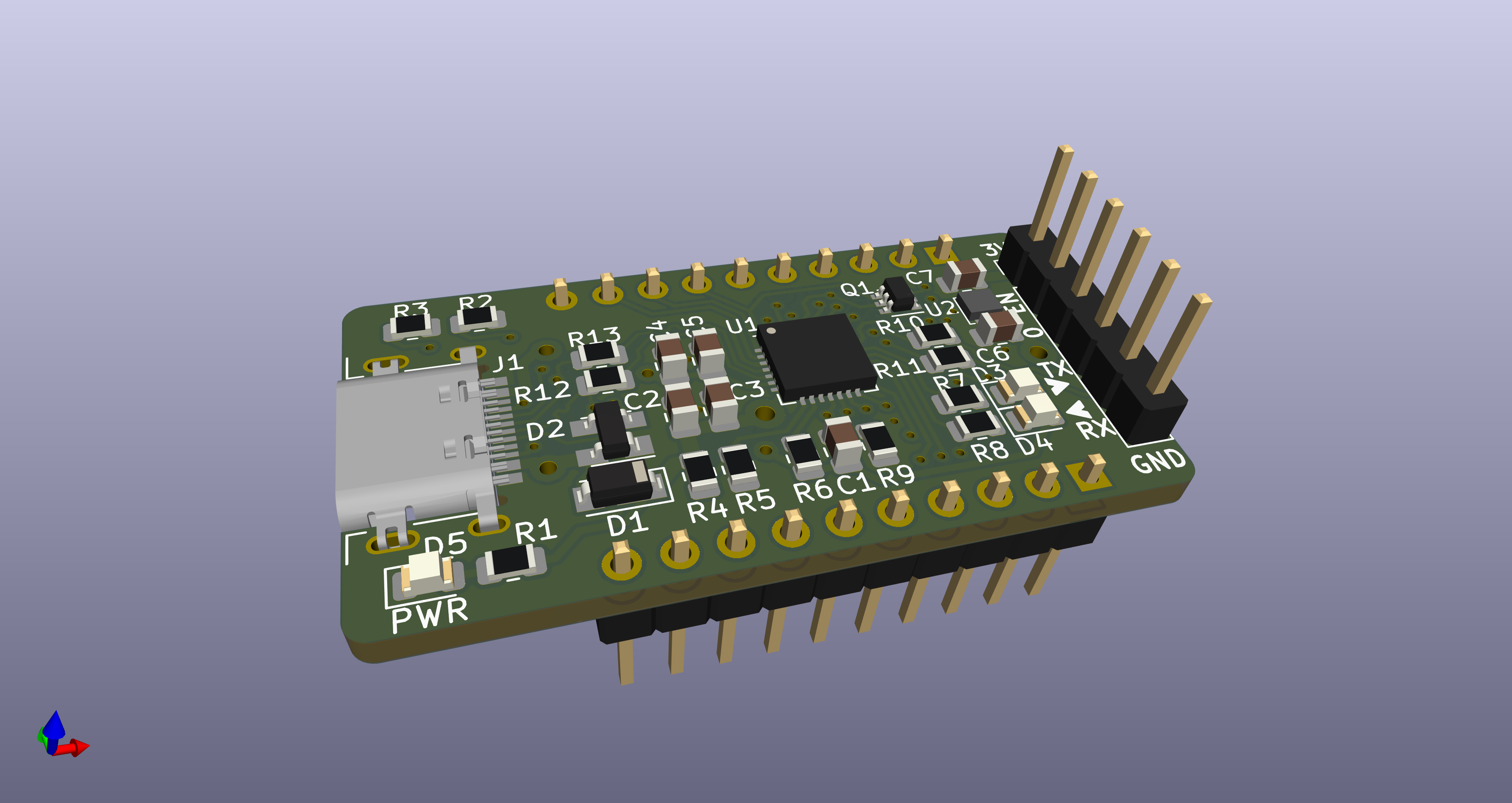
| Top View | 3D Rendering | Bottom View |
|---|---|---|
 |
 |
 |
Features
- USB-C Connector: Modern USB-C interface for reliable power and data connection (USB 2.0)
- CP2102N Bridge Chip: High-performance USB to UART bridge controller (up to 3 Mbaud)
- High-Power LDO: Dedicated XC6220B331ER regulator providing up to 1A at 3.3V for connected devices (the CP2102N operates directly from USB 5V)
- Status LEDs: Visual indicators for Power (PWR), Transmit (TX), and Receive (RX)
- UART Breakout: Dedicated 6-pin UART connector with standard pinout
- Extended GPIO Access & Breadboard Compatibility: Exposes extra CP2102N GPIO pins via dual 10-pin headers, designed for direct insertion into standard breadboards to simplify prototyping and expand control options
- Auto-Reset Circuit: Dual MOSFET transistor circuit enables automatic reset of the connected microcontroller during programming
- Compact Form Factor: Optimized 2-layer PCB layout with surface-mount components (0805 package size)
Interactive Bill of Materials
Note
Explore components to view details and placement information. View Fullscreen 🔍
Technical Documentation
3D Model
Note
Explore the 3D model interactively. Use mouse to rotate, zoom and pan. View Fullscreen 🔍
Detailed Pinout Reference
UART Connector (J3)
Note: In ESP8266 and ESP32 family chips, their GPIO0 pin is used to control boot mode (e.g., entering flash mode for programming). The labeled GPIO0 pin in this connector is intended to be connected to the target chip’s GPIO0 pin to control the boot mode. This usage may not apply to other target chips, so verify your specific hardware requirements.
| Pin | Function | Description |
|---|---|---|
| 1 | 3V3 | 3.3V Power Output |
| 2 | EN | Enable/Reset |
| 3 | GPIO0 | Boot mode control |
| 4 | TXD | UART Transmit |
| 5 | RXD | UART Receive |
| 6 | GND | Ground |
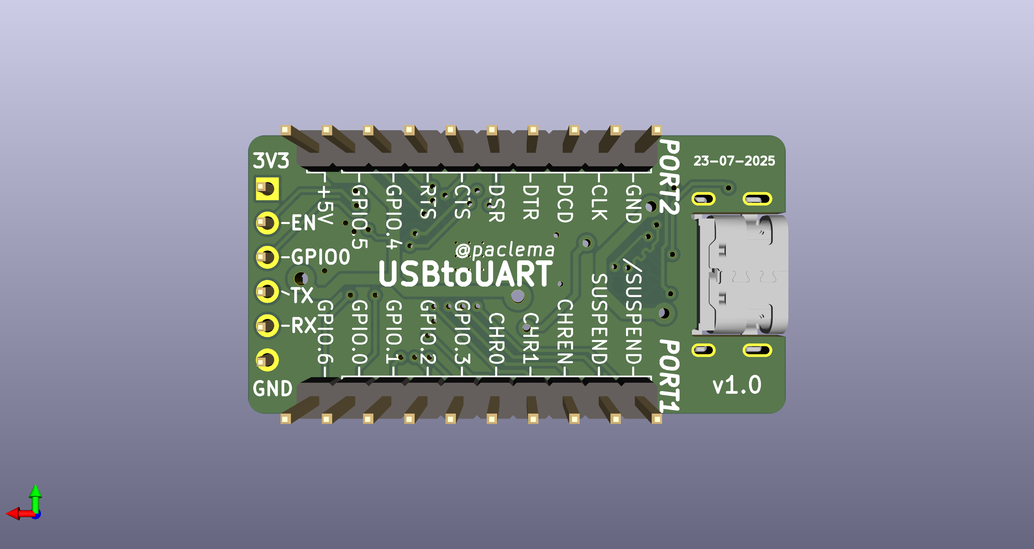
Extended Port Connectors
- 10-pin male headers providing access to power rails (3.3V, 5V, GND) and CP2102N GPIO signals
- Enable powering and controlling external circuits directly from the board
- Compatible with standard breadboard and prototyping setups
- Standard 2.54mm (0.1") pin spacing
PORT1 (J2)
| Pin | Function | Description |
|---|---|---|
| 1 | GPIO.6 | CP2102N GPIO 6 |
| 2 | GPIO.0 | CP2102N GPIO 0 |
| 3 | GPIO.1 | CP2102N GPIO 1 |
| 4 | GPIO.2 | CP2102N GPIO 2 |
| 5 | GPIO.3 | CP2102N GPIO 3 |
| 6 | CHR0 | Battery Charging Detection 0 |
| 7 | CHR1 | Battery Charging Detection 1 |
| 8 | CHREN | Battery Charging Enable |
| 9 | SUSPEND | USB Suspend State |
| 10 | /SUSPEND | USB Suspend State (Inverted) |
PORT2 (J4)
| Pin | Function | Description |
|---|---|---|
| 1 | +5V | 5V Power Output (from USB connector) |
| 2 | GPIO.5 | CP2102N GPIO 5 |
| 3 | GPIO.4 | CP2102N GPIO 4 |
| 4 | RTS | Request To Send |
| 5 | CTS | Clear To Send |
| 6 | DSR | Data Set Ready |
| 7 | DTR | Data Terminal Ready |
| 8 | DCD | Data Carrier Detect |
| 9 | CLK | Clock output |
| 10 | GND | Ground |